|
||||

A Research Organization
|
||||
|
|
See archived newsletters for previous stages as they happened. www.eagle-research.com/newsletter/archive/2001/2001_10.php www.eagle-research.org/newsletter/archive/2001/2001_12.php www.eagle-research.org/newsletter/archive/2002/2002_02.php www.eagle-research.org/newsletter/archive/2002/2002_04.php www.eagle-research.org/newsletter/archive/2003/2003_04.php www.eagle-research.org/newsletter/archive/2003/2003_08.php www.eagle-research.org/newsletter/archive/2004/2004_04.php www.eagle-research.org/newsletter/archive/2004/2004_08.php For the time being, these pages are acting as a 'supplement' to the newsletter information. The newsletters contain much detail not included here.We will be upgrading these pages into a regular feature on the website. In the meantime, only our newsletter subscribers can enjoy this preview. Stage 1: Insert a fuel filter into the fuel hose before fuel pressure regulator and carburetor (preferably before fuel pump). We prefer transparent filters so we can see when they need changing. 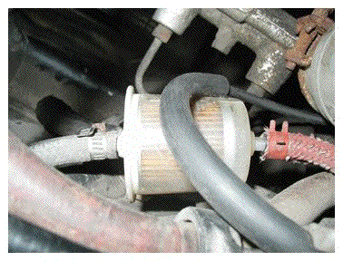
Stage 2: Insert a fuel pressure regulator into the fuel hose just before the carburetor. Adjust it to the lowest fuel pressure that will give you no performance problems. In this case we use 1 psi. 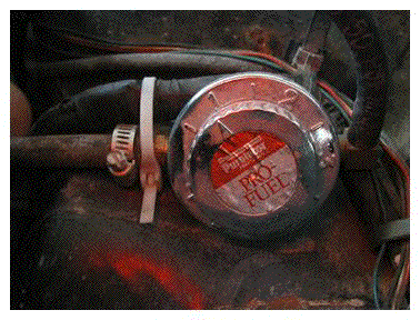
Stage 3: Install a vacuum gauge on the dash. We installed it where the clock would have been, so we had access to battery, ignition, lights and ground wires. 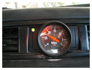 Do a neater job than I did. I miscalculated the depth of my hole saw and the frame of the saw cut into the dash vinyl. Later, as I was taking the plastic frame in and out, I broke it and had to plastic weld it. It is stronger than original but isn't yet returned to factory look. Note the green LED that indicates the deceleration fuel shutoff circuit has shut off the fuel. This light tells you when you are saving fuel by not even putting it into your engine. We installed this LED when we put in the automatic (rpm version) deceleration fuel shutoff. Do a neater job than I did. I miscalculated the depth of my hole saw and the frame of the saw cut into the dash vinyl. Later, as I was taking the plastic frame in and out, I broke it and had to plastic weld it. It is stronger than original but isn't yet returned to factory look. Note the green LED that indicates the deceleration fuel shutoff circuit has shut off the fuel. This light tells you when you are saving fuel by not even putting it into your engine. We installed this LED when we put in the automatic (rpm version) deceleration fuel shutoff.
Stage 4: Install a manually operated deceleration fuel shutoff switch. We put ours right on the shifter so that we could easily turn the fuel on and off. This will (in combination with the vacuum gauge and the tachometer) start to give you the idea of under what conditions you can shut off your fuel with no performance problems. We found that we could shut off the fuel whenever the engine rpm was greater than 1200 rpm and we didn't have my foot on the throttle (deceleration). Note: This Honda already had a tachometer. You do not need (though we recommend it) a permanent vacuum gauge and tachometer. You can hook up temporary ones that you remove after all adjustments are complete. The switch on the shifter can be removed after installation and adjustment of the automatic version of the deceleration fuel shutoff is complete.  We hooked the manual deceleration fuel shutoff switch to the 'anti-dieseling' solenoids on the carburetor. These solenoids are normally closed, opening with ignition power. It was a simple matter to put the switch in the power wire (leading to both solenoids) to turn them off at will. We hooked the manual deceleration fuel shutoff switch to the 'anti-dieseling' solenoids on the carburetor. These solenoids are normally closed, opening with ignition power. It was a simple matter to put the switch in the power wire (leading to both solenoids) to turn them off at will.  Most carburetors do not have this anti-dieseling 'advantage'. In those you need to install the Carburetor Enhancer with the deceleration upgrade (Detailed in the Carburetor Enhancer Literature). All our recommended techniques shut off the fuel going OUT of the carburetor; leaving the float bowl full of fuel and ready for instant power when you need it. We do NOT recommend shutting off the fuel going INTO the carburetor because the float bowl will empty and will require a few seconds to refill once you turn the fuel back on. For electronic fuel injection deceleration shutoff you need to use the Electronic Diverter (detailed in HyCO 2A literature). Most carburetors do not have this anti-dieseling 'advantage'. In those you need to install the Carburetor Enhancer with the deceleration upgrade (Detailed in the Carburetor Enhancer Literature). All our recommended techniques shut off the fuel going OUT of the carburetor; leaving the float bowl full of fuel and ready for instant power when you need it. We do NOT recommend shutting off the fuel going INTO the carburetor because the float bowl will empty and will require a few seconds to refill once you turn the fuel back on. For electronic fuel injection deceleration shutoff you need to use the Electronic Diverter (detailed in HyCO 2A literature).
Stage 5.1: Now that we had the parameters needed to take maximum advantage of deceleration fuel shutoff. We designed a circuit based on several switches. We have deliberately not used the vacuum switch circuits as per our earlier literature because we find this rpm version to be more efficient in actual driving conditions. For example, it does not have to be readjusted when the weather changes or when changing altitude, it shuts off the fuel during times when you are truly in deceleration but not maximum deceleration and it turns the fuel back on a fraction faster. For simplicity we designed the circuit to turn the fuel 'off' as a default (using a p-channel mosfet with a positive 'pull-up' signal to the gate) and use normally closed 'grounding' switches to keep the fuel turned on. P-channel mosfets turn ON when their gate is grounded. All the normally closed switches are placed so that they become 'open' when its OK to have the fuel turned off. (1) foot off throttle (2) foot off clutch (3) rpm greater than set point (user adjustable) (4) engine warm (choke pushed in) The circuit will NOT shut off the fuel if any one (or more) of these switches is grounding. (circuit schematics shown below) Note: There already was a brake switch but we've found we don't need to use it. It is OK to apply the brakes during deceleration fuel shutoff. In fact, the brakes are more effective (and wear less) because they are not having the engine 'driving' against them as you are trying to stop. Your brakes last longer and you need them less (because engine deceleration is now more effective in slowing you down without brakes). Stage 5.2: We took out the rubber bumper for the clutch pedal and used the hole to hold a bracket to mount the clutch switch. The first clutch switch we installed was noisy and the constant 'clicking' was very unacceptable for the driver. The switch we now have is highly reliable, small, inexpensive and quiet in operation. Most modern vehicles (with manual transmissions) already have a clutch switch so that the starter will not engage if the clutch is not pressed in. You should be able to use this switch. If it is not a 'grounding' switch, you can use the 'reversal' circuit we detail in several of our manuals (like the HyZor Technology). 
Stage 5.3: We then installed an 'store bought' rpm switch. (Later we show you a 'home built' circuit that is just as effective and a lot less expensive). Stage 5.4: Now we installed a throttle position switch. Again, it is a normally closed switch that is quiet in operation. The bracket took a little time to make and install. Stage 5.4: Now we installed a throttle position switch. Again, it is a normally closed switch that is quiet in operation. The bracket took a little time to make and install.  (Note: All torch work was done with an ER1200 WaterTorch) Note: Wiring is temporarily tied out of the way until the installation is done and it can be loomed neatly. Stage 5.5: Install a means to shut off the deceleration fuel shutoff when the engine is cold. This can be done lots of ways. You could use switches on any linkage, temperature switches from the engine or the temperature switch on some electric carburetor chokes. This is our 'opps' for the project. We discovered that when the choke is pulled out, the cold idle rpm is over 1200. Thus the deceleration fuel shutoff 'saw'; foot off clutch and throttle and rpm over 1200 so it would shut off the fuel. The circuit worked great, but we couldn't keep the engine on :)) We needed to shut off the circuit when the engine was at 'cold' high idle. We discovered that the manual choke on this car included a 'grounding' switch so that it lights up a 'idiot light' on the dash (telling me that the choke is on). We simply tapped into it (as per the schematics), problem solved. (Note: All torch work was done with an ER1200 WaterTorch) Note: Wiring is temporarily tied out of the way until the installation is done and it can be loomed neatly. Stage 5.5: Install a means to shut off the deceleration fuel shutoff when the engine is cold. This can be done lots of ways. You could use switches on any linkage, temperature switches from the engine or the temperature switch on some electric carburetor chokes. This is our 'opps' for the project. We discovered that when the choke is pulled out, the cold idle rpm is over 1200. Thus the deceleration fuel shutoff 'saw'; foot off clutch and throttle and rpm over 1200 so it would shut off the fuel. The circuit worked great, but we couldn't keep the engine on :)) We needed to shut off the circuit when the engine was at 'cold' high idle. We discovered that the manual choke on this car included a 'grounding' switch so that it lights up a 'idiot light' on the dash (telling me that the choke is on). We simply tapped into it (as per the schematics), problem solved.  Stage 5.6: Installing a 'manual bypass switch ' on the circuit. This bypasses the mosfet and turns the fuel on. This is mandatory on all 'enhancements' that could affect the performance of the vehicle in driving conditions. Also when you may be having other drivers in the vehicle while you are adjusting parameters (trouble shooting). We simply used the same switch we had for the manual fuel shutoff, now wired to bypass the mosfet. Once we have the circuit working flawlessly (and invisible to the normal driver), we will coil it up and tie it neatly under the dash. Note: in our case, a slight pull out on the choke (enough to light the dash light but not enough to actually choke the car) will 'act' as a shutoff to the system and keep the fuel turned on (assuming the mosfet is working). Stage 5.7: Building and installing the mosfet circuit/s as shown. The 'Power' mosfet (P1) s an IRF9Z34, a P-channel mosfet in a TO-220AB case design. It can handle (with proper heat sink) 13 amps at 100°C. It is rated for a maximum drain to source voltage of -60 volts (making it very okay for a 'nominal' 12 volt system). 'N1' and 'N2' are IRFD014, N-channel mosfets in a HEXDIP case design. Can handle 1 amp at 100°C. Is rated for a maximum drain to source voltage of 60 volts. We like using HEXDIPS because they are circuit board mounted mosfets, taking up little room. They work great when low amperage switching is required. You can use any equivalent n-channel mosfet, including the ones in a TO-220 case style from Radio Shack. All resistors are 1/4 watt rated or greater. R10 is 100,000 ohm. R14 needs to be minimum 400 ohm. We use a 1000 ohm potentiometer (do not adjust for less than 400 ohm). It is OK to put a fixed 400 ohm resistor in series with the R14. R15 needs to be minimum 400 ohm. We use a 1000 ohm potentiometer (do not adjust for less than 400 ohm). It is OK to put a fixed 400 ohm resistor in series with the R15. S2 is any SPST switch that can handle the solenoid current. We mounted it on the shifter for easy access while driving. RPM Switch. We show both the 'store-bought' MSD Ignition Products RPM Activated Switch Kit (part # 8950) with the Adjustable RPM Module (part # 8677) and the Home-Buildable circuit we are designing. S3 is the normally closed (NC) clutch switch. We ultimately used a 'Niehoff' brake switch acquired at 'Lordco' (a local auto parts store). It was used on Volvo 70-92, Saab 67-75, Geo 89-91 and BMW 70-88. S4 is the NC throttle switch. We used a brake switch we got off some vehicle in the past and had in our 'surplus switch' bin in the shop. You can use the same style switch as S3. S5 is the OEM choke switch, we just tapped into it as per the schematic. D2 is IN4002 diode. 1 amp. 100 volts or greater. Note that we use chip sockets, they save a lot of trouble. For those people who don't have fuel shutoff solenoids on their carburetors; where our circuits say 'Fuel Solenoids', you could send the 'positive' signal to the ECE to shut the fuel off. If you have electronic fuel injection, send the positive signal to an N-channel mosfet reversing circuit (not shown) to activate fuel shutoff using the Electronic Diverter. Stage 5.6: Installing a 'manual bypass switch ' on the circuit. This bypasses the mosfet and turns the fuel on. This is mandatory on all 'enhancements' that could affect the performance of the vehicle in driving conditions. Also when you may be having other drivers in the vehicle while you are adjusting parameters (trouble shooting). We simply used the same switch we had for the manual fuel shutoff, now wired to bypass the mosfet. Once we have the circuit working flawlessly (and invisible to the normal driver), we will coil it up and tie it neatly under the dash. Note: in our case, a slight pull out on the choke (enough to light the dash light but not enough to actually choke the car) will 'act' as a shutoff to the system and keep the fuel turned on (assuming the mosfet is working). Stage 5.7: Building and installing the mosfet circuit/s as shown. The 'Power' mosfet (P1) s an IRF9Z34, a P-channel mosfet in a TO-220AB case design. It can handle (with proper heat sink) 13 amps at 100°C. It is rated for a maximum drain to source voltage of -60 volts (making it very okay for a 'nominal' 12 volt system). 'N1' and 'N2' are IRFD014, N-channel mosfets in a HEXDIP case design. Can handle 1 amp at 100°C. Is rated for a maximum drain to source voltage of 60 volts. We like using HEXDIPS because they are circuit board mounted mosfets, taking up little room. They work great when low amperage switching is required. You can use any equivalent n-channel mosfet, including the ones in a TO-220 case style from Radio Shack. All resistors are 1/4 watt rated or greater. R10 is 100,000 ohm. R14 needs to be minimum 400 ohm. We use a 1000 ohm potentiometer (do not adjust for less than 400 ohm). It is OK to put a fixed 400 ohm resistor in series with the R14. R15 needs to be minimum 400 ohm. We use a 1000 ohm potentiometer (do not adjust for less than 400 ohm). It is OK to put a fixed 400 ohm resistor in series with the R15. S2 is any SPST switch that can handle the solenoid current. We mounted it on the shifter for easy access while driving. RPM Switch. We show both the 'store-bought' MSD Ignition Products RPM Activated Switch Kit (part # 8950) with the Adjustable RPM Module (part # 8677) and the Home-Buildable circuit we are designing. S3 is the normally closed (NC) clutch switch. We ultimately used a 'Niehoff' brake switch acquired at 'Lordco' (a local auto parts store). It was used on Volvo 70-92, Saab 67-75, Geo 89-91 and BMW 70-88. S4 is the NC throttle switch. We used a brake switch we got off some vehicle in the past and had in our 'surplus switch' bin in the shop. You can use the same style switch as S3. S5 is the OEM choke switch, we just tapped into it as per the schematic. D2 is IN4002 diode. 1 amp. 100 volts or greater. Note that we use chip sockets, they save a lot of trouble. For those people who don't have fuel shutoff solenoids on their carburetors; where our circuits say 'Fuel Solenoids', you could send the 'positive' signal to the ECE to shut the fuel off. If you have electronic fuel injection, send the positive signal to an N-channel mosfet reversing circuit (not shown) to activate fuel shutoff using the Electronic Diverter. 
With the deceleration circuit schematic in hand, do the initial 'look over' of your vehicle. Discover where you will be getting your power from (ignition and battery), where you will grounding the circuit/switches and where all the components will be located. Then you will know what length/color/gauge to make the wires. We prefer to put the electronics under the dash. You may want to consider designing the components so they are removable in case you change vehicles and want to take them with you. The board on the right is the original circuit (Fig 01) with the LED brightness pot (tan square). The board on the left is the modification we added (Fig. 02) to make the MSD output snap action; the pot sets the rpm 'sensitivity' for the 'snap action'. Use different colored wires (color code) and stick to it. Color code will help installation and later troubleshooting. Make detailed notes on the schematic the instant you make any changes. Assume that you are instructing someone that knows NOTHING of what you are doing. If you are like me, you will forget some details in the years to come and waste time 'relearning' the circuit when you go to work on it. Keeping a copy of the notes in the glove box (with the vehicle papers) is a very good idea. We included a potentiometer (Fig. 01, R15) to control the brightness of the dash mounted green LED3. It is variable from 400 to 10,000 ohm. Again, you do not have to dash mount this LED; you could just mount it on the circuit board to assist when adjusting the switches. I recommend doing both, as per LED2 and LED3. LED2 is mounted on the circuit board and does not need a brightness control. It makes it simple to adjust the rpm switch because you can see it easier than looking back and forth to the dash. However, if you have an assistant that can watch the tachometer and LED3, then LED2, R14 and N2 are not needed on the circuit. We like to have LED3 on the dash because it helps us 'readjust' our driving habits; mostly using the engine to decelerate instead of the brakes and remembering to take our foot completely off the throttle during deceleration. It is really a satisfying feeling to see the green LED light up. With practice it can be lit up quite often. In some driving conditions we can go many miles at highway speeds with it lit (fuel shut off). The board on the right is the original circuit (Fig 01) with the LED brightness pot (tan square). The board on the left is the modification we added (Fig. 02) to make the MSD output snap action; the pot sets the rpm 'sensitivity' for the 'snap action'. Use different colored wires (color code) and stick to it. Color code will help installation and later troubleshooting. Make detailed notes on the schematic the instant you make any changes. Assume that you are instructing someone that knows NOTHING of what you are doing. If you are like me, you will forget some details in the years to come and waste time 'relearning' the circuit when you go to work on it. Keeping a copy of the notes in the glove box (with the vehicle papers) is a very good idea. We included a potentiometer (Fig. 01, R15) to control the brightness of the dash mounted green LED3. It is variable from 400 to 10,000 ohm. Again, you do not have to dash mount this LED; you could just mount it on the circuit board to assist when adjusting the switches. I recommend doing both, as per LED2 and LED3. LED2 is mounted on the circuit board and does not need a brightness control. It makes it simple to adjust the rpm switch because you can see it easier than looking back and forth to the dash. However, if you have an assistant that can watch the tachometer and LED3, then LED2, R14 and N2 are not needed on the circuit. We like to have LED3 on the dash because it helps us 'readjust' our driving habits; mostly using the engine to decelerate instead of the brakes and remembering to take our foot completely off the throttle during deceleration. It is really a satisfying feeling to see the green LED light up. With practice it can be lit up quite often. In some driving conditions we can go many miles at highway speeds with it lit (fuel shut off). 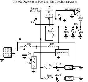 We discovered that the MSD rpm switch was not 'snap action'. It shuts off in a 'pulse width modulated' fashion over a range of a couple of hundred rpm. This would cause the solenoids to 'chatter' on and off in that rpm range. This is OK (and recommended) when using it with solenoid valves specified for the Electronic Carburetor Enhancer (or the ED); because they are rated for fast cycling and continuous operation. But this is not good for the 'anti-dieseling' solenoid valves on this Honda carburetor, so we added some circuit components (Fig, 02) to make the MSD rpm circuit 'snap action'. The 358 (dual op-amp) is set up as a very sensitive voltage comparator. The 358 monitors C6 voltage and compares the voltage to a set point voltage (R12). The output signal (pin 7) is normally low (negative) which keeps P1 turned 'on' and (grounds the gate) of Fig. 01, P1; keeping the fuel turned on. R13 is 56,000 ohm. R11 is 1,000 ohm. R12 is 500,000 ohm pot. C6 is about 30 uF. ----------------- Alternate 'home buildable' RPM Switch (click here) We discovered that the MSD rpm switch was not 'snap action'. It shuts off in a 'pulse width modulated' fashion over a range of a couple of hundred rpm. This would cause the solenoids to 'chatter' on and off in that rpm range. This is OK (and recommended) when using it with solenoid valves specified for the Electronic Carburetor Enhancer (or the ED); because they are rated for fast cycling and continuous operation. But this is not good for the 'anti-dieseling' solenoid valves on this Honda carburetor, so we added some circuit components (Fig, 02) to make the MSD rpm circuit 'snap action'. The 358 (dual op-amp) is set up as a very sensitive voltage comparator. The 358 monitors C6 voltage and compares the voltage to a set point voltage (R12). The output signal (pin 7) is normally low (negative) which keeps P1 turned 'on' and (grounds the gate) of Fig. 01, P1; keeping the fuel turned on. R13 is 56,000 ohm. R11 is 1,000 ohm. R12 is 500,000 ohm pot. C6 is about 30 uF. ----------------- Alternate 'home buildable' RPM Switch (click here)
 |
 |
||
|
|
|
||||||||
